Maximum Weld Table, Minimum Effort!

Hydraulic lift weld table

I’ve wanted to build a proper weld table for quite a while now.  This project has gone through several iterations in my head and just about the time I’m ready to buy the materials…

Hydraulic Lift Table
Lift table before modification

I find this awesome old hydraulic lift table on Craigslist.  And bam! Just like that my long considered plans are discarded, and I collect the dividends of my procrastination.  A phone call and short drive later I’m thrusting a fist full of cash at the gentlemen who was delusional enough to sell such a fine piece of obtainium.

From what the seller tells me, this came from Lewis Air Force Base up in Washington state.  He had purchased three of these at a government auction several years back.  He included a pigtail with a rocker switch that plugs into the twist lock at one end of the table and runs the table up and down well enough.  I will be adding a foot operated paddle switch in the future along with a safety “ratchet” mechanism.  But for now I have some welding projects to get moving on… so this installment is to just make it functional as quickly as possible.

Descaling Hot Rolled Plate
Letting the acid work on the scale

I had a piece of 1″ hot rolled plate hi-def plasma cut to 72″ X 36″ and hauled it home.  I decided to try removing the mill scale with phosphoric acid… and it helped, but needed much more “soak time” than I (or the weather) was interested in providing.  I removed most of the mill scale with a wire wheel and various stripping type wheels on an angle grinder.  This left some swirl marks here and there but nothing that removed any measurable amount of metal.  It’s as flat a one can expect from hot rolled and resulted in a really nice surface to work on.

The top of the lift table was about 2′ X 6′ and I wanted the 1″ plate work surface to extend beyond the supporting structure on all sides to allow for easy clamping, so I trimmed down the ends of the lift table.

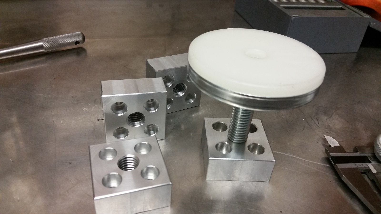
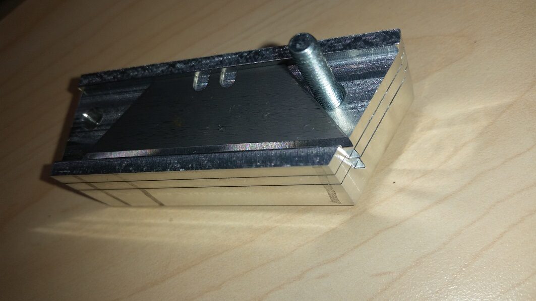
I wanted to create a little bit of space between the bottom of the 1″ steel plate and the top of the lift table, so I built these riser mounts.  This makes a convenient shelf space for vise grips, sharpies, tape measures and all the other small things that are nice to have close at hand for welding and fab work.

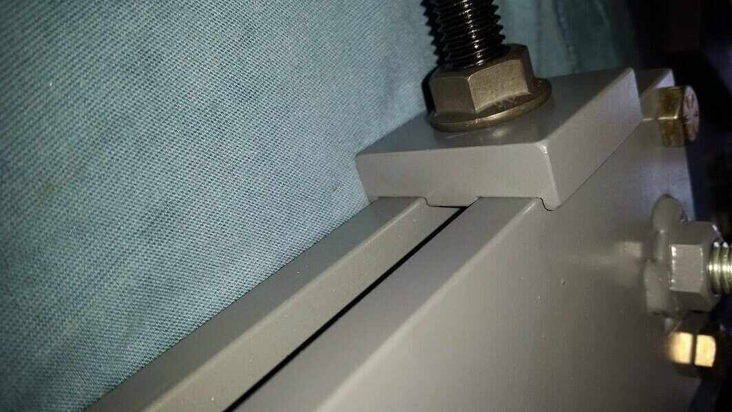
Next up was drilling and countersinking the 6 mounting holes in the work surface.  I carefully measured & scribed my hole pattern, then center drilled, through drilled, and countersunk the holes.  The 1/2″-13 flat heads sit just a hair below the surface of the steel plate.

Mounts welded
Mounts Welded

I bolted the riser mounts to the bottom of the plate, lined the lift table up underneath, and picked er up.  After tacking the mounts to the lift table I unbolted the plate and set it back on the jack stands.   I welded out all six mounts then reinstalled the plate.

Final result
Not too shabby!

I’m really happy with how this turned out, especially considering how little effort it required to bring together.  The hydraulic lift table was a really lucky find and eliminated a ton of work.  I was originally planning a fixed height welding table on casters… this is sooo much nicer and was far less work.

Clamping ability
Maximum clampiness!

The 1″ plate is stiff enough to allow for the large overhang on all sides.  This makes it really nice to clamp parts in place for welding.  As you can see there is plenty of room on the end to accommodate the full depth of the deep throat Vise Grips.

When lowered all the way, the work surface sits about 11″ off the floor, and raised all the way sits right at 48″.  This is a real back saver when getting heavy things on and off the table.  It’s also super nice for the small fiddly stuff because I can raise it way up and don’t need to be hunched over.  Additionally it’s been useful for getting heavy stuff in and out of truck beds, reaching things on high shelves, amusing small children… don’t try this at home… seriously people… I’m not Mr safety… not even close… you’ve been warned!

As I mentioned earlier, I will probably revisit this later to refine some of the details.  I plan to add a safety ratchet mechanism and a foot operated switch to raise and lower.  For now I really appreciate having a flat & true surface to weld on.  It’s also super nice to be able to ground through the table and not have a ground clamp constantly in the way.

Hydraulic lift weld table
I am now totally spoiled!

Bridgeport BOSS CNC Control Retrofit Part 1 (Intro)

I picked up an old Bridgeport BOSS CNC mill a while back.  It has spent the last few years languishing in the corner of my buddy Jon’s shop.  Prior to that it was supposedly prototyping parts destined for Harley Davidson.  After an offhand inquiry one day, it was offered up for sale.  A bit of research convinced me that I was just enough of a glutton for punishment to add it to my project list.

Y axis Bridgeport ways
Dusty… but nice ways

The bones of the machine are actually in pretty nice shape.  The table is devoid of idiot marks.  The ways still have their chrome, and the ballscrews all look really nice.  The spindle runs smooth & quiet all the way up to it’s 4500 RPM maximum.  It’s apparent that this machine was well cared for.

The control and power cabinets are excessively large by today’s standards, but nicely constructed.  A close examination serves as a testament to the care and competence once embodied by America’s workforce.  Wires are all well labeled and neatly run.  Airflow within the cabinets is well thought out.  The build quality is representative of a time when companies weren’t so pressed to squeeze every stray penny of cost savings out of a product, and could build to a higher standard.  I couldn’t help but get a bit nostalgic when looking these over.  It’s going to be a little sad to gut them, but times change and a new control system will ultimately save this machine from the scrap heap for another couple decades or more.

Blueprint of BOSS schematic
Schematic

The original hand drawn schematics in true “blueprint” form are still with the machine and are super cool.  The neatness of the drawings puts my chicken scratch to shame.  The drawings are all still readable despite a bit of mouse chewing here and there.

CNC Control:

No doubt it was state of the art when it was new in 1977, but it’s in serious need of updating now.  There are lot’s of options out there in the DIY CNC realm and it took a fair bit of research to decide which direction I wanted to go with it.  For a few hundred bucks, one can install some Gecko drives and retain the original steppers.  This setup can be controlled with an old PC and a Mach3 installation.  Near the high end of the price range are the Centroid retrofit kits at somewhere north of $11,000.

Operator panel – with single line display

The goal for this project is not only to put an old machine back into useful service, but to improve it’s capabilities in the process.  The factory stepper motors on this machine are only capable of 0.001″ resolution, so the stepper motors are going away and the low budget option along with them.  The Centroid kits look pretty nice but the cost puts me within spitting distance of just purchasing a good used CNC with the same or better capabilities.  Besides, if I did a bolt on kit there wouldn’t be much to learn or to write about.  This mill makes for a convenient platform to get me started building CNC controllers, which happens to be another goal of doing this retrofit.

It was decided that the right solution was to roll my own using various commercially available components.  The axis motors will be replaced with servos.  A new CNC controller will be assembled to suit the application.  The enormous cabinets will get removed along with all unnecessary components, and the machine will get completely re-wired.

This isn’t going to be a high priority project for me, so updates will come along on a “whenever I get to it” sort of schedule.  I do plan on covering the various aspects in detail though.  So keep checking back and you’ll occasionally find a new write up.


Liteplacer Build Part 3

Partially built pick & Place machine

The third installment in this series covers the construction of the frame/enclosure and the wiring of the machine.  Check out part 1 and part 2 of the build if you haven’t already.

Frame Rendering

I decided to build a dedicated frame & enclosure for my Liteplacer rather than mount the machine to a table like it was designed.  Since the plan is to add feeders and other features over time as needs evolve, the added cost of 80/20 extrusion seems justified.  I had previously designed the frame in Solidworks and the extrusions were ordered cut to length.  All that was left to do was drill a few holes, tap some of the ends and assemble.


Hole drilling with Bridgeport mill
Drilling Holes

Speaking of tapping… why is it that you never seem to break a tap when you have a spare?  But always seem to when you don’t.  Murphy’s law of course came into play… and I ended up donating my only 5mm tap to the scrap bin.

Liteplacer Enclosure Frame With Controls
Assembled Frame With Controls Mounted

Putting this all together necessitated the manufacture of several parts.  A total of 12 custom brackets were manually machined on the ole Bridgeport.  Mounts for the footpads, monitor, PC, and the brackets to mount the Liteplacer into the enclosure were created.  There is something uniquely satisfying about using machinery to build more machines, but all the handle turning really had me wishing for a CNC… more on that in a future post.

The Liteplacer mounts into the frame with a machined bracket at each corner.  I also made up a center bearing support out of some 0.125″ aluminum.  This supports the Y axis shaft center bearing from the frame, and allows removal of the Liteplacer’s rear crossbar.

Cables connected to control enclosure
CNC Control connections

With the machine mounted, it was time to wire it up.  Continuous flex rated cable was used for all the moving runs of wire.  I found some Trex-Onics 18AWG / 6 conductor shielded cable on ebay that was reasonably priced.  The axis motors and limit switches were all wired in using this shielded cable.  The cables were terminated at the control end using Amphenol C 091 A Series connectors to mate up to the control box.

Relocation bracket for Y axis cable guide
Cable guide bracket

The Y axis cable carrier ran a little long for my enclosure and was going to hit the front cover when the Y axis came all the way forward.  I cut a piece of 0.125″ aluminum and formed up a relocation bracket to move the mounting point rearward which afforded me plenty of room.

While the 80/20 extrusion is really nice for it’s adaptability, it doesn’t make for a particularly rigid frame without cross bracing it.  You’ll notice in the picture and rendering at the top of this post that I’ve added some aluminum panels to the bottom, rear and sides of the machine.  In addition to better enclosing the machine, these serve as structural elements, effectively cross bracing the machine in all three directions.  The polycarbonate covers on the upper portion of the machine will also add a bit of rigidity, albeit to a lesser extent than the aluminum panels.

The plates are 0.125″ 5052 aluminum, and the pan that sits just under the open bed area is 0.080″.  These parts were laser cut at a local shop that also did the forming of the “bed pan”.  The polycarbonate covers are 3/16″ thick, and used up an entire 4′ X 8′ sheet.  I laid these out in Solidworks and pestered my buddy Jon until he cut them on his router table.

Most of the polycarbonate covers won’t be installed until the rest of the details are sorted out and the machine is up and running.  I’ve got at least one or two more posts worth of details to cover before the machine is finished.  I still need to build and mount the vacuum reservoir.  I also need to build circuit board and parts holders.  Then it will be time to load software and start placing components.  Thanks for reading and keep an eye out for updates.

Liteplacer Build – Part 2

For part two I’m going to cover the building/assembly and wiring of my custom control electronics enclosure for the Liteplacer.  Part one of this series can be found here, and covers the mechanical assembly of the Liteplacer kit.

I designed this enclosure in Solidworks after some careful measuring of all the goodies that go inside.  With .dxf files in hand, I paid a visit to my buddy Jon and his big router table.  The large vented backplate was cut from 0.125″ aluminum, the end panels and cover were cut from 0.060″.  The engraving of the end panels was done on the router table using a diamond point tool.  The width of the control box matches the small HP computer that will mount vertically just below.

Next order of business was to fire up my little press brake and put the appropriate bends in these freshly cut parts.

I’m pretty happy with how all the pieces ended up fitting together.  I could have made the enclosure just a tad longer though, since it got a little tight inside by the time everything was mounted & wired.

The power supply I used is a 10A/24VDC Delta unit, which happens to be a bit overkill but it’s what I had to work with.  Also, since I’m going to be running a larger 12VDC powered vacuum pump rather than the one that comes with the kit, I mounted a small 12VDC power supply inside.

The vacuum configuration I’m going to run will include a reservoir and an adjustable vacuum switch to power the pump only when needed.  This necessitated a couple changes to the way the vacuum pump FET was wired up.  I ended up using some IRF3708’s for the pump and solenoid valve instead of the STD30NF06L FET’s that were included with the Liteplacer kit.  I put together a perf board to hold these goodies, and mounted it to a couple of the available threaded holes in the big power supply.  The 1N4007 freewheeling diode in the diagram above will be mounted at the vacuum pump motor rather than the perf board for the sake of simplicity.

Connections to the stepper motors, limit switches, solenoid valve, vacuum pump, vacuum switch, and LED ring lights are brought out the rear panel via Amphenol C 091 A Series connectors in 3, 4, and 6 pin varieties.

The USB connector on the Tiny-G board lines up nicely with the provided opening.  One cable gland secures the incoming power cord, and the other is for the IEC pigtail that brings AC power back out to the PC.  The one thing I neglected to consider when designing the enclosure was a place to provide power for the monitor.  I fixed this by manually cutting a square hole in the 0.125″ backplate to accommodate a single AC outlet.  This works but it did make the area behind the front panel more cramped than I had planned.

The front panel houses a pair of lighted rocker switches.  One provides power to the machine via the main power supply, and the other controls power to the vacuum pump.  Three push to reset circuit breakers reside along the bottom.  These provide independent protection for the machine power, the vacuum pump, and the PC/Monitor.  While certainly more than required protection wise, it is nice to have things broken out like this when it comes time to troubleshoot a problem.

The emergency stop I used is a GCX1131 from Automation Direct.  I currently have it wired up to the reset input on the Tiny-G motion control board like is shown in the Liteplacer instructions.  However I’ll probably be changing this to interrupt power to the 24VDC supply instead.  If you look closely you’ll notice that I have a green contact block (normally open) on the e-stop.  This works for resetting the board, but it’s a no no in the industrial control world because the machine won’t stop if a wire in the safety circuit comes loose.  The Liteplacer instructions do however make a point to mention this issue.

With the enclosure all buttoned up, the next step of the project will be to assemble all of my nice new 80/20 extrusion to create the frame that will house everything.  I’ll also need to make up some brackets to mount the PC.  That’s all for today, thanks for reading!

Liteplacer Build – Part 1

I have to admit that placing surface mount components by hand was never my favorite thing.  It’s an activity that’s tolerable if a person only needs a couple of small boards here and there.  However it is quickly becoming a dreaded activity as I have found myself faced with more frequent production runs of 20 or 30 boards, and larger component counts.  For example, I have a control board design that will be ready to prototype in a few weeks that has a component count somewhere in the 300+ neighborhood.  The thought of assembling one of these by hand was enough to get me seriously looking at pick and place machines.

I spent a fair bit of time evaluating the options on the budget end of the spectrum and decided to order up a Liteplacer kit.  I considered everything from designing and building my own machine, to buying a ready to run commercial machine.  The design it myself route was going to take more time than I can afford to devote to such a project right now.  The commercial machines are faster and have more features but came along with a higher cost and a larger footprint.  What attracted me to the Liteplacer is that it’s just enough machine for what I need right now, plus it’s open source & DIY friendly so I can add some of the more advanced features myself as time goes on and needs change.

This first installment is going to be a pretty basic overview of the Liteplacer.  Subsequent articles will cover wiring the machine, and some of the custom touches I’ll be adding during the build.

So… what do you get when you order one of these?

Two boxes full of neatly bagged labeled parts, plus all the makerslides & extrusions to build the machine to the point of being able to attach it to your work surface.  Also included are the cameras for the machine vision functionality, and the Tiny-G motion control board.  It is up to the end user to independently source things like cabling, power supply, monitor, PC, enclosures, and work surface/supporting structure.

There’s not much to say about the mechanical assembly process really.  It was all pretty easy, and well laid out in the instructions.  The detailed labeling was a real help throughout the assembly process too.  The process actually reminded me a bit of assembling a new set of Legos, or Erector sets as a child.

Here’s a closer look at the Y axis drive.  Note: I have not added the belting yet.

Here’s a peek at the gantry.

I added the optional cable carriers when I ordered the kit.  The carriers come a little bit longer than necessary and will hang out in the Y direction.  This isn’t a problem if you are mounting the machine “open air” style like most people do.  However I’m planning to have this machine enclosed, so I shortened up the Y axis cable carrier a bit to reduce the footprint.

The nozzle holder is laser cut from stainless steel and overall, pretty nice.  The included magnets do a good job of retaining the nozzles.  It’s simple yet elegant.


The next step is to build the enclosure for the control electronics and the frame/enclosure for the entire machine.  I drew both of these up in Solidworks.  I’ll be mounting a 21.5″ ASUS monitor on the top horizontal member of the frame.  The PC is a used small form factor HP that will mount vertically just under the control electronics enclosure on the inside left of the machine.

I was originally planning to do a welded steel frame to support the machine, but opted instead for 80/20 extrusion for the added flexibility as I add features over time.

This is the enclosure seen at the left of the frame assembly above.

That’s all for today.  I’ll be posting additional articles as progress moves forward.


Custom Puller Tools

Here is a pair of custom puller tools that I recently designed and built for a customer.  These are used to remove impellers from large centrifugal irrigation pumps.

I designed these to use commonly available hardware for all the wear parts.  The central nut is a grade 8 coupling nut, and the jacking screw is 5/8-18 grade 8 threaded rod.  The central nut is captured in a machined pocket between the side plates and rests against a thrust plate that spans the side plates and locks into a slot in either side.


The top plates saddle over the side plates to prevent the sides from spreading under a heavy load.  The customer will be using two different threaded rods on the sides to attach to the pumps (1/2″-13 & 3/8″-16.)  So I drilled the center hole at 1/2″ and made the counterbore to fit the 3/8″-16 flange nut so the plate will hold either size centered.


This project turned out to be a little more time consuming than I originally predicted.  I am however happy with the results – simple, and effective, with commonly available wear parts.

Label Slicer Tool

This is my first post in what I expect will become a series detailing some useful small scale manufacturing techniques.  Anyone who attempts to bring niche products to market will find that there are unique challenges in producing small product volumes.  Many times the low volume makes outsourcing much of the assembly and production work cost prohibitive while the time requirements of using low cost manual techniques in the modest home shop can quickly get out of hand when faced with fulfilling orders of 10, 20, or 50 of your product.  If you are working a full time job and building widgets on the side, the prospect of coming home from a full workday and facing another 6 to 10 hours of work before bedtime gets old FAST!

So… what is the inventor and entrepreneur to do?  The answer is to get smart (efficient) with our manufacturing techniques and our time.  In these posts I will show what that age old adage of “work smarter not harder” looks like when the rubber meets the road and it’s put in to practice.  Ok, enough with the preamble and on to the meat of the post.

This turned out to be a handy & simple little tool.  I made this a while back, when I was faced with the challenge of trimming down a bunch of labels (about 100) and applying them to these screw terminals.  After doing a couple with scissors and being less than satisfied with the results I decided a better way was needed.  I messed around with some different widths of tape in the label maker, but anything that was narrow enough to fit the terminals resulted in text that was so small as to be nearly unreadable.

So… I ended up printing two rows of labels on a 3/4″ label tape and building this nifty little custom slicer tool to cut them to a uniform and repeatable width.

This little bugger uses standard utility knife blades, so when they get dull its a just a matter of loosening the machine screws and replacing them.

I think the pictures pretty much explain things here.  The blades sandwich in between the machined parts that provide the proper spacing and the whole works is held together with two machine screws.  The “guide block” has a groove machined into it to hold the label and the nose of the cutter is machined to run inside this grove to guide it down the label.

The pictures show the labels being cut face up, this however resulted in some light marring on the face.  I ended up cutting the labels face down so the cutter runs across the backside and the face remains clean & professional looking.  If you don’t have access to machining equipment, I think this idea would work equally well if done with a 3D printer.

Another Reflow Toaster Oven Build

WARNING!! This project involves hazardous voltages, high temperatures, sharp edges & risk of injury or death and is inherently unsafe.  There are plenty of tutorials out there for anyone looking to build their own reflow oven, this post isn’t meant to be a tutorial.

With that said… here is my take on the reflow toaster oven.

I found myself in need of a small reflow oven that I could do low volume production and prototype quantities in.  The small commercial units were priced in the thousands, and didn’t offer any features I couldn’t implement myself.  So I browsed the various homebrew reflow ovens on the web and set off to make my own.  I grabbed this little Black & Decker from Amazon and got to work.

It’s fairly small with a wire rack that measures about 11.5″ wide X 9″ deep.  This allows me to run several small boards at once or, one or two medium sized PCB’s at a go.  The small footprint fits nicely on the workbench too!

First order of business was to fire it up and see what it would do.  Temperature control is via a simple bimetallic thermostat that regulates based on the air temperature behind the control panel, which is walled off from the oven chamber with a single piece of sheet metal.  This struck me as an odd arrangement, but I’m replacing all of that anyway so it doesn’t really matter.

Initial testing

I grabbed my trusty Fluke meter and threw a thermocouple inside to see what the internal temps maxed out at.  The bimetal thermostat opens at about 530 F, at which point the temp would drop a couple dozen degrees before closing again.  Temperature regulation that is probably fine for reheating pizza, but it just won’t do for PCB assembly.

A look at the factory wiring and controls

During initial testing I also noted the apparent lack of insulation and the single wall construction on the rear and bottom of the unit which made for an external temperature in the melt your skin off range.  This issue will be addressed shortly.

A little probing around with the multimeter & tracing wires and I had a schematic to start with.


Factory wiring configuration


The three circles on the left represent the three knobs on the front panel.  The four heating elements are shown at the top center of the page.  The bimetallic thermostat switches the AC hot leg, and the timer switches the neutral.  The function switch selects between various modes of operation.  Note the diode connected to the top elements.  The diode acts as a half wave rectifier when the elements are connected through the diode and provides a reduced power output setting.  The oven also provides a bypass around the diode for full power output from the top heating elements.  I’ll be retaining the heating elements and convection fan, the rest is getting gutted.

Single wall back panel

With the factory controls removed, it was time to start insulating the box.  The goal here was to keep heat losses to a minimum for efficiency and provide for an even temperature distribution within the oven.

The single wall back panel was the first to be addressed.

This panel had a conveniently placed “bump out” so I sliced off a piece of rockwool to fit and made up an interior panel out stainless.

I added a fairly heavy cross break to this panel to increase stiffness and provide just a little more room for insulation.  It is held in place by the same screws that hold the back panel in place.


Providing further challenges to the insulation task was the single wall bottom panel of the oven.  However there was a “bump out” similar to the back panel, and a crumb tray with a matching bump out.  I cut the front lip off the crumb tray, flipped it over, drilled some holes and screwed it down with a bit of insulation in the resulting cavity.

Insulating the left side of the oven.  In the first picture you can see the ends of the heating elements and the spring that holds the door closed.  A little careful trimming and this side is done.

The right side insulation gets a little more involved since I need to work around the convection fan, and also leave room for installing the new controls in this space.  I made up several insulation retaining bales using stainless filler rod.

I built the new control on a Parallax Propeller project board and sprinkled it with various goodies.  Internal oven temperature is monitored with two k type thermocouples hanging on a piece of stainless wire just above the wire rack.  Thermocouples are being read via the MAX31855 on Adafruit’s handy breakout board.  A DS1620 also resides on the board to monitor the temperature inside the control enclosure space.  The Propeller monitors the temperature and turns the case fans on and off to keep temps reasonable.  The convection fan is also controlled by the microcontroller via a relay soldered onto the board.

Space is a little tight so things are shoehorned in, but it all fits.  In the following picture you can see how its all laid out.  Control board at top left, cooling fans at top right.  Note the high tech Altoid tin insulation shield to keep the insulation from being pulled into the cooling fans.  DC power supply at bottom right (white box) provides 12VDC for control power.  The black relay zip tied to the power supply is a safety shutdown for the heaters.  It is wired into a bimetallic thermostat buried under the insulation and will drop out in the case of a control system failure and thermal runaway.  Heater current is switched via the solid state relay seen at bottom left.

Control system layout

User interface consists of a rocker switch at the bottom of the front panel for system power.  The red button pulls the safety relay in when pressed, thereby “arming” the heaters.  The relay is wired to self latch when this button is pressed, and stay latched unless a thermal runaway event trips the safety thermostat.  The rest of the user interface is via a resistive touchpanel from 4D Systems.

The touchpanel has a lot of capabilities that I’m not currently using.  The software running this oven is pretty basic at this point but it gets the job done.  Temperature regulation is via PID and is working really good.  Reflow curve parameters are user adjustable via on screen menus.  At some point I’ll write an update and throw some more features in & make the display a bit prettier too.  I’m planning to add in a graph of the temperature during reflow into the large open space in the center of the home screen shown above.

The insulation helps a lot too.  The exterior still gets warm during repeated extended use, but it no longer has the ability to instantly sear flesh.  As of the time of this writing this oven is still going strong.  It has even assisted in a couple of Kydex holster making projects at this point.